UI Specifications
Actually, I insist that I don’t do wireframes. Oh, sure, I do lots of drawings that serve the same purpose, and I often summarize what I do for clients by describing them in this way. However, I work with different teams all the time, and within UX practice areas, the term wireframe still seems to mean a black-and-white vector comp. It’s pretty much just a drawing of a page.
I create UI Specifications. A few other designers that I have encountered do similar work, but I am the only one I know of who insists on using that term. There are some obvious practical reasons, mostly having to do with the argument about drawing versus prototyping. From too much bad experience, I fall firmly on the side of show and tell. As shown in Figure 1, a UI Specification has both drawings and lots of words, tables, and numbers to tell implementation teams how to get to the drawing and how to make it move. It has annotations on the left and a table of colors below the high-fidelity drawings on the right. And don’t forget timings and behaviors. We create interactions, not just user interfaces.
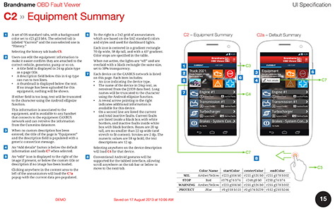
Perhaps the key reason that I actually call them specifications is that it helps User Experience to be part of the conversation. We don’t do drawings; we specify a key part of the process, and we’ll open bugs against any parts that Engineering doesn’t do right.
A few weeks ago, I talked to a developer at Garmin. This was interesting because, while I have plenty of friends there, his process was totally different from theirs, and design got baked inviolably into the process. He doesn’t work on Web sites or apps, but on aviation systems—cockpit design and so on. They don’t have designers, but human-factors engineers. I have had this title on my business cards and worked with people who went to school to get degrees in this discipline. This is really what we do every day—even for apps and Web sites and the rest of our non-life-threatening work.
As long as we take our UX work seriously, pursue our work with scientific rigor, and tell everyone else in an organization that is what we do, we can make surprising headway. Specifications get taken seriously.
Yes, I know that, after all, UI stands for user interface, but the term UX Specification was pushing for mass-market understanding. No one parses that title that deeply, so this is still my name for the deliverables that I produce.
Programmatic Design
More and more, I find that specifying user-interface designs is crucial. The reason that this is so is one of the key things now making our applications and Web sites look good: we don’t need to embed so many images anymore. I haven’t 9-sliced anything in years.
Instead, we can programmatically specify lots of things. Need a different color for the title in your iOS app? Just change the tint color for the Navigation Bar. Need anything at all to be a gradient on a Web page? CSS now supports gradients on almost any component. For example, Figure 2 shows a diagram of a title bar in red, while the annotations specify its color and how to display it correctly.
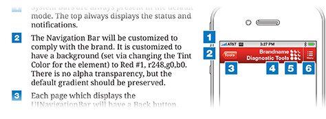
I have built entire apps and Web sites with just one embedded graphic: the logo. And that only because we really can’t render a logo programmatically. The future is even more promising, but that’s a topic for another day.
My specifications are full of words describing everything. While I still sometimes create wireframe-style, grayscale boxes and lines; more often, I just do everything at full fidelity, then specify how to get there, including the component or method, the sizes—both the physical sizes of the elements in a design and a scalable unit for the platform—the colors, transparency, and so on.
Scale and Math
Scale is one thing, units of measurement are another; and this is where InDesign helps us all out. It supports pretty much any unit. Pick the one you are most comfortable with. Since I started with print design, I use picas and points. I still even own and use pica sticks.
What’s even better is that InDesign doesn’t lock you into a particular unit. Even when units are set to points, I can type 5 cm in the Width box. The box will then switch to displaying 141.732 pt—but only after first resizing the object to 5cm. It’s still the same physical size. If you didn’t already know that iPhone screens are all 5 cm wide, this is a good thing to know. I didn’t deliberately memorize this, but after typing it in a few times, I remembered it. Working at scale makes me think at device and human scale all the time.
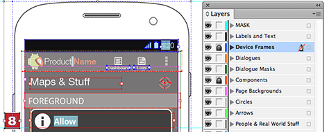
When specifying physical sizes, this makes things easy. You just follow your guidelines for text size and add that information to your annotations. Even for other sizes—say converting to Apple points or Android dp / sp—just figure out your scaling ratio and make a note at the side of your document about that. Visio gets confused by this, but InDesign lets you place drawing objects outside the print area—whether to organize them, save things, or leave yourself notes. I often do this, as shown in Figure 3, where I’ve included an optional design, a reminder of the brand angle with which everything must align, and a list of items to fix in the design.
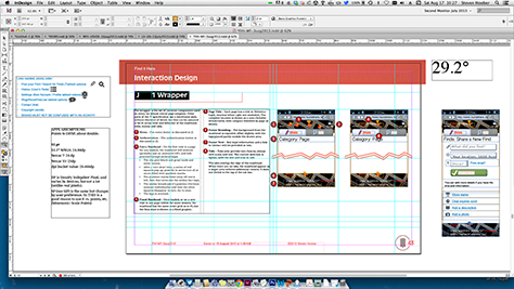
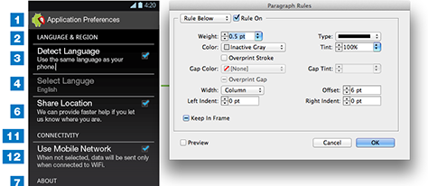
You can even do simple math in the Size and Scale fields. Just type directly into the fields, as shown in Figure 4. Want a box that’s as wide as the screen to be half as wide? Divide the width in half by typing /2 after the current size, then pressing Enter. This is a great way to resize things without using scale panels. If you aren’t enough of a mathematician, a slash indicates division; an asterisk, multiplication. All of these symbols must precede the unit label. These fields don’t accept complex formulas, so don’t try to use parentheses and so on.

Layers
If you’ve worked in any serious drawing tool in the past decade, you know about layers. If you are used to Adobe Photoshop, be aware that layers are a bit different in vector tools. Each layer is more like a group of layers. You can draw each object on its own level and can move it forward and backward within the layer. Or you can draw everything in the single, default layer, and it will look just fine.
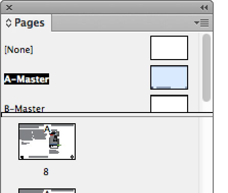
But if you organize your drawings better, things become really easy. Let’s say you’re working on a dialog box. If you put that in a Dialog Box layer, when messing with it, you can lock or hide Components, Backgrounds, and Device Frames layers. Color coding each layer helps you to identify which layer you currently have selected, so if it’s not locked, you can be sure that you’ve grabbed the right object. See Figure 5 for an example of how I organize my drawings in layers, with different objects on layers that correspond to the layers of key UI elements.
